DMX 3 DCSSR
Design
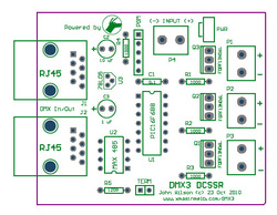
The board is a simple design, there are two sections to the design; the DMX controller, and the DCSSR.
The DMX controller consists of the Comms IC and the microprocessor, PIC 16F688. The SSR section of the board is simply just a FET per channel.
Euro style screw connectors are specificed for the board, and they are grouped in pairs (+/-) to make connections easy.
They are labeled P1, P2, and P3.
The power input for the Flood light section of the board is via P4.
The DMX3 DCSSR is designed to switch DC loads between 0 and 60 Volts. The MOSFETs are rated to 10 Amps each, however as fitted to the PCB, I would limit to individual channel load to 2 to 3 Amps max. A suitable heatsink may be required.
Power Options
The Logic side of the board is designed to operate from a regulated power supply provided by 78L05 regulator. Bypass capacitors (C2, C3) are fitted for the regulator. The DMX3 board can be powered using a number of options:
1. Via the CAT5 Cable and P4. This is the 'normal' operation for the board. 12 VDC is injected into the CAT 5 with the DMX signal, and is routed to the 78L05 regulator. Power for the SSR section is connected to P4.
2. Via P4. Both the Controller and SSR sections of the board can be powered via P4, negating the need to inject power via the CAT5. A jumper is required for this option. The jumper is located to the right of P4, and is labelled PWR on the overlay. The minimum voltage required for this option is 8 VDC. While I have not tested this option above 24 VDC, the maximum rated input for the regulator is 35 VDC. In practice, the power dissipation by the reulator would be of concern.
3. Via CAT 5 only. This is similar to Option 2. The jumper is required to be fitted to the board at PWR. The limitation for this option is the current capacity of the CAT 5. The rated current capacity of a single pair of CAT 5 is 0.577 amps. The board uses three pairs and therefore the maximum current capacity of the cable would be 1.7 amps. Remember, while the cable may be able to handle this current, it will be spread across all of the DMX3 DCSSRs connected in this manner.
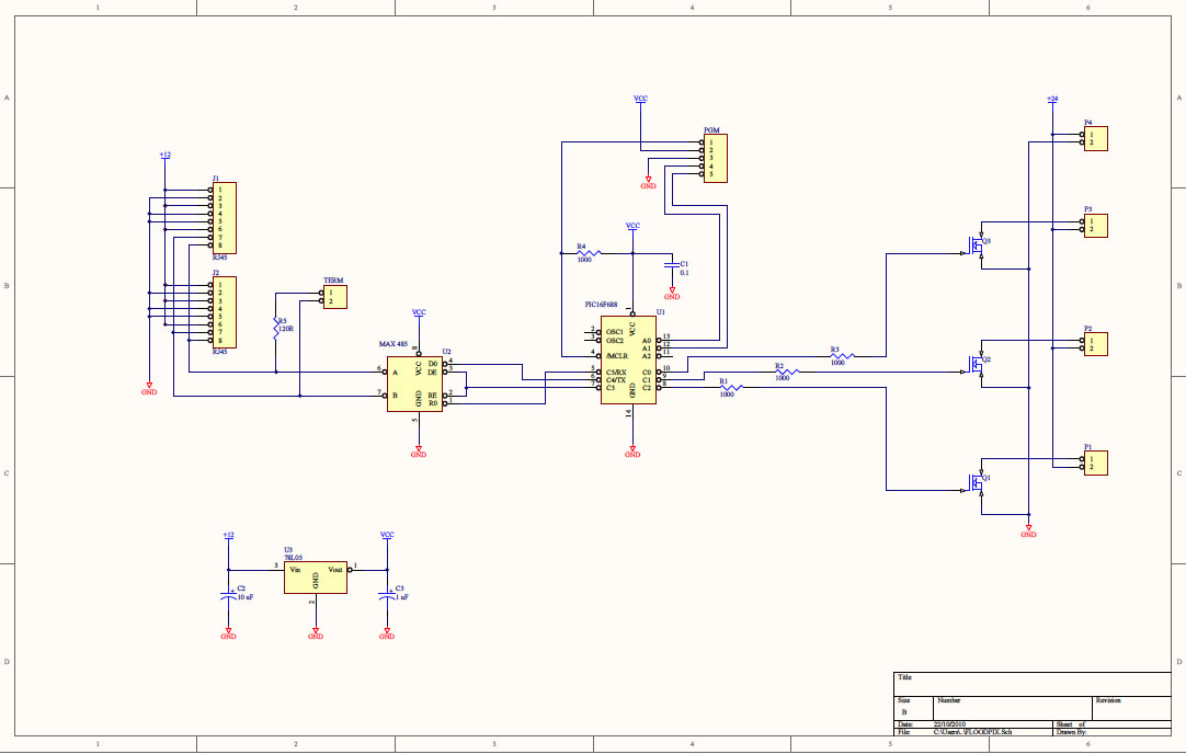
Schematic
The schematic for the board is available. Click here to load it
Parts List
I have a parts list in Word. Click here to load it.
I have built a Parts List BOM in Mouser. Click here to load it.
Some parts are optional, IC sockets can be deleted as can P1-4, depending on the power and load connections,
R5 Carbon Film Resistors - 120 ohms .
Printed Circuit Board
A circuit board for the DMX3 DCSSR is available for sale.
The board is a simple design, there are two sections to the design; the DMX controller, and the DCSSR.
The DMX controller consists of the Comms IC and the microprocessor, PIC 16F688. The SSR section of the board is simply just a FET per channel.
Euro style screw connectors are specificed for the board, and they are grouped in pairs (+/-) to make connections easy.
They are labeled P1, P2, and P3.
The power input for the Flood light section of the board is via P4.
The DMX3 DCSSR is designed to switch DC loads between 0 and 60 Volts. The MOSFETs are rated to 10 Amps each, however as fitted to the PCB, I would limit to individual channel load to 2 to 3 Amps max. A suitable heatsink may be required.
Power Options
The Logic side of the board is designed to operate from a regulated power supply provided by 78L05 regulator. Bypass capacitors (C2, C3) are fitted for the regulator. The DMX3 board can be powered using a number of options:
1. Via the CAT5 Cable and P4. This is the 'normal' operation for the board. 12 VDC is injected into the CAT 5 with the DMX signal, and is routed to the 78L05 regulator. Power for the SSR section is connected to P4.
2. Via P4. Both the Controller and SSR sections of the board can be powered via P4, negating the need to inject power via the CAT5. A jumper is required for this option. The jumper is located to the right of P4, and is labelled PWR on the overlay. The minimum voltage required for this option is 8 VDC. While I have not tested this option above 24 VDC, the maximum rated input for the regulator is 35 VDC. In practice, the power dissipation by the reulator would be of concern.
3. Via CAT 5 only. This is similar to Option 2. The jumper is required to be fitted to the board at PWR. The limitation for this option is the current capacity of the CAT 5. The rated current capacity of a single pair of CAT 5 is 0.577 amps. The board uses three pairs and therefore the maximum current capacity of the cable would be 1.7 amps. Remember, while the cable may be able to handle this current, it will be spread across all of the DMX3 DCSSRs connected in this manner.
Schematic
The schematic for the board is available. Click here to load it
Parts List
I have a parts list in Word. Click here to load it.
I have built a Parts List BOM in Mouser. Click here to load it.
Some parts are optional, IC sockets can be deleted as can P1-4, depending on the power and load connections,
R5 Carbon Film Resistors - 120 ohms .
Printed Circuit Board
A circuit board for the DMX3 DCSSR is available for sale.
